Cracked Iron and Redemption: A Tale of the MITERS Hardinge HLV Lathe
23 May 2025
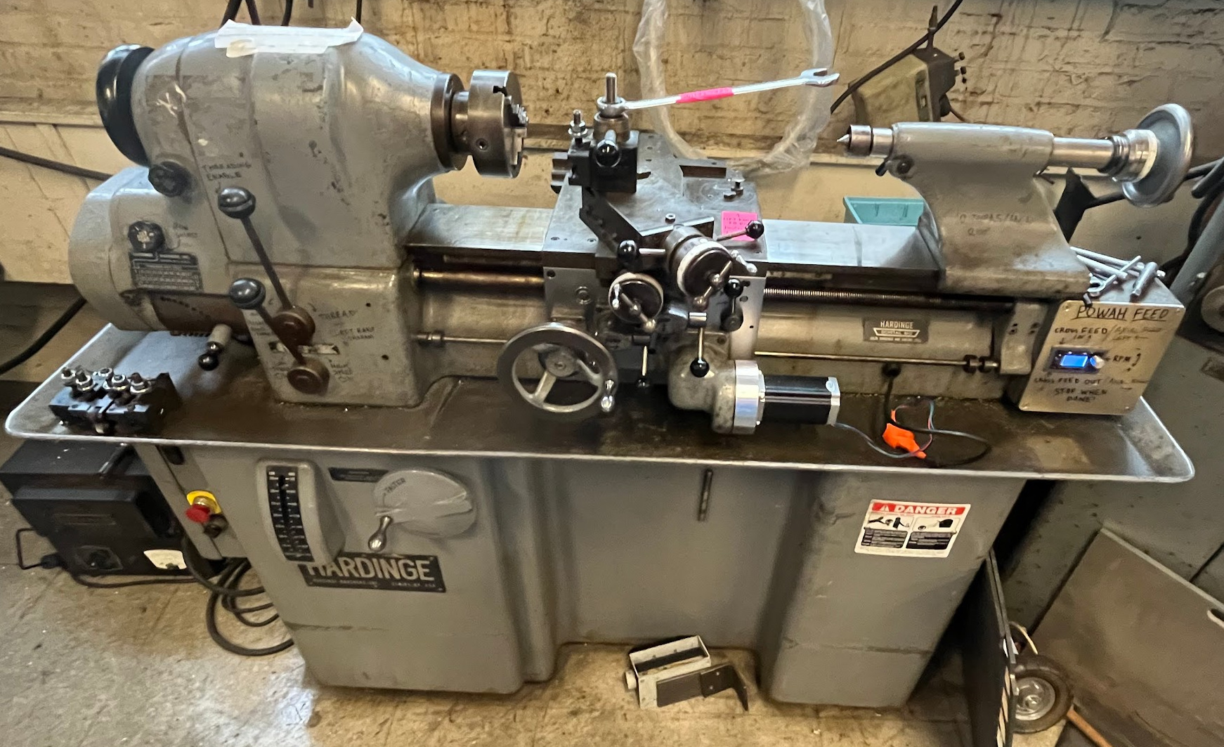
MITERS is a you-break-it, you-fix-it kind of a shop. This applies to things big and small, and sometimes, you break something big—like an irreplaceable, 1950s vintage toolroom lathe. This is the story of a repair attempt gone wrong: how I broke in half—and then remanufactured—the apron cover on the MITERS Hardinge HLV lathe.
I have a soft spot for machine tools—elegant works of cast iron and steel, shaped by the hands of skilled craftsmen from an era before our disposable, plastic world. To be entrusted with such a tool is to bear a responsibility: to preserve it, to repair it, and to pass it on to the next generation in better condition than it was received.
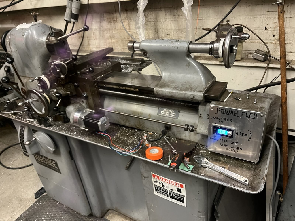
Our story begins with one such repair attempt on the MITERS Hardinge HLV lathe. I had replaced the original shunt-wound power feed motor (the field windings of which had burned out long ago) with a stepper motor, but there was a problem—only the power cross feed worked. The longitudinal feed clutch was jammed and would not engage. To fix it, I would have to open the apron cover to unjam a sliding bar that interlocks the half nut and longitudinal feed. I searched for the maintenance manual, and found one for the HLV-H—close enough, I figured—and set to work. As it would turn out, “close enough” was not close enough…
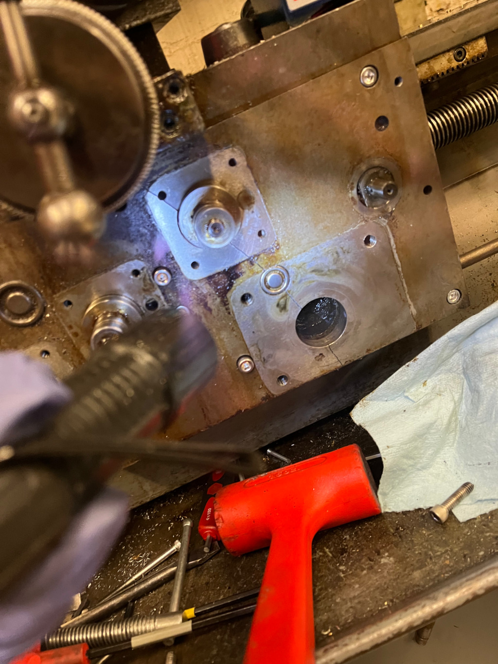
The HLV-H manual claims the apron cover can be removed while the main apron casting is still attached to the lathe, unlike most other lathes, where the assembled apron is first removed from the saddle before removing the cover. That’s why, late one IAP evening, I found myself crouched in front of the lathe, tools strewn everywhere, trying everything I could think of to remove the apron cover. The cover was quite stubborn—no matter what I did, I could not pull it more than a fraction of an inch off the main casting. I pried and I hammered, and pried some more… all to no avail. In desperation, I resorted to drilling and tapping threaded holes into the cover, through which I threaded screws to push off the apron.
As it turns out, that was a Bad Idea™. As I tried to force the cover loose with these pusher screws, I heard a sickening crack, and I saw—to my horror—that the apron cover had cracked in two.
This was catastrophic.
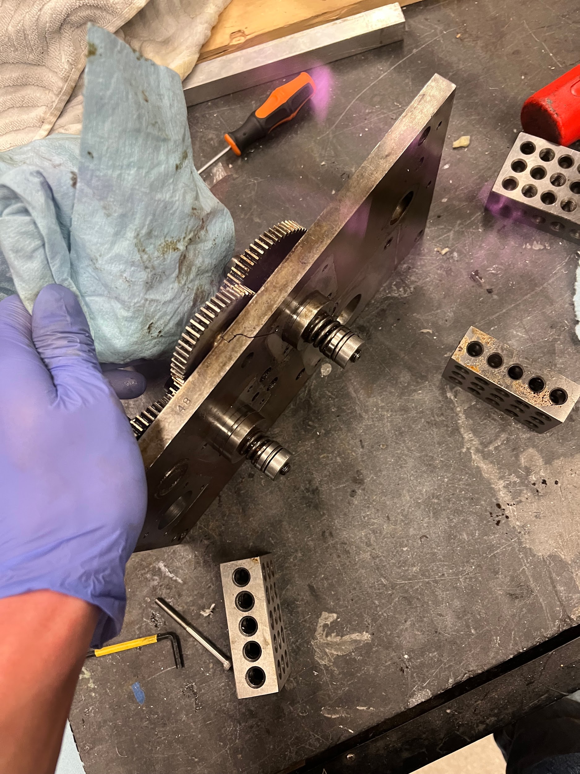
It turns out that Hardinge substantially changed the apron design between the HLV and HLV-H models, so the apron cover could not be removed directly on the HLV—instead, the whole apron assembly needed to be removed as a unit first.1 By this point I had finally realized this, so I decided to do things the right way. I removed the power feed box, lead screw and stop rod from the right side of the machine, and then unbolted the four socket head screws attaching the apron to the saddle. There were two alignment pins that were a tight fit, but when I worked those loose, the apron assembly dropped easily (a little too easily—I managed to crush my finger in the process—ouch!). From there, removing the cover was a breeze, especially as it was now cracked in two so it could no longer bind!
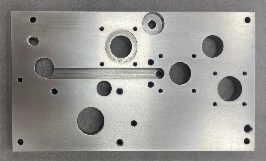
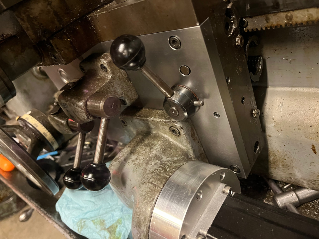
Here are some pictures of the cracked cover after removal (the two halves are being held together by some accumulated gunk):
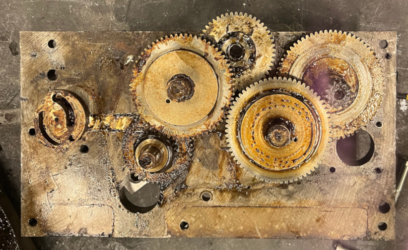
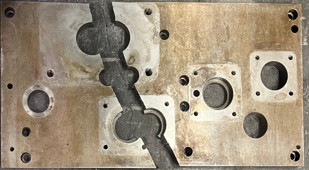
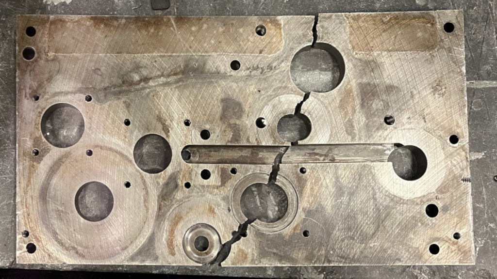
I was extremely fortunate that I had only cracked the apron cover plate, and not the main apron casting itself. Had I done the opposite, the whole lathe could have been ruined—damaging the main casting itself would probably have been beyond my ability to fix.
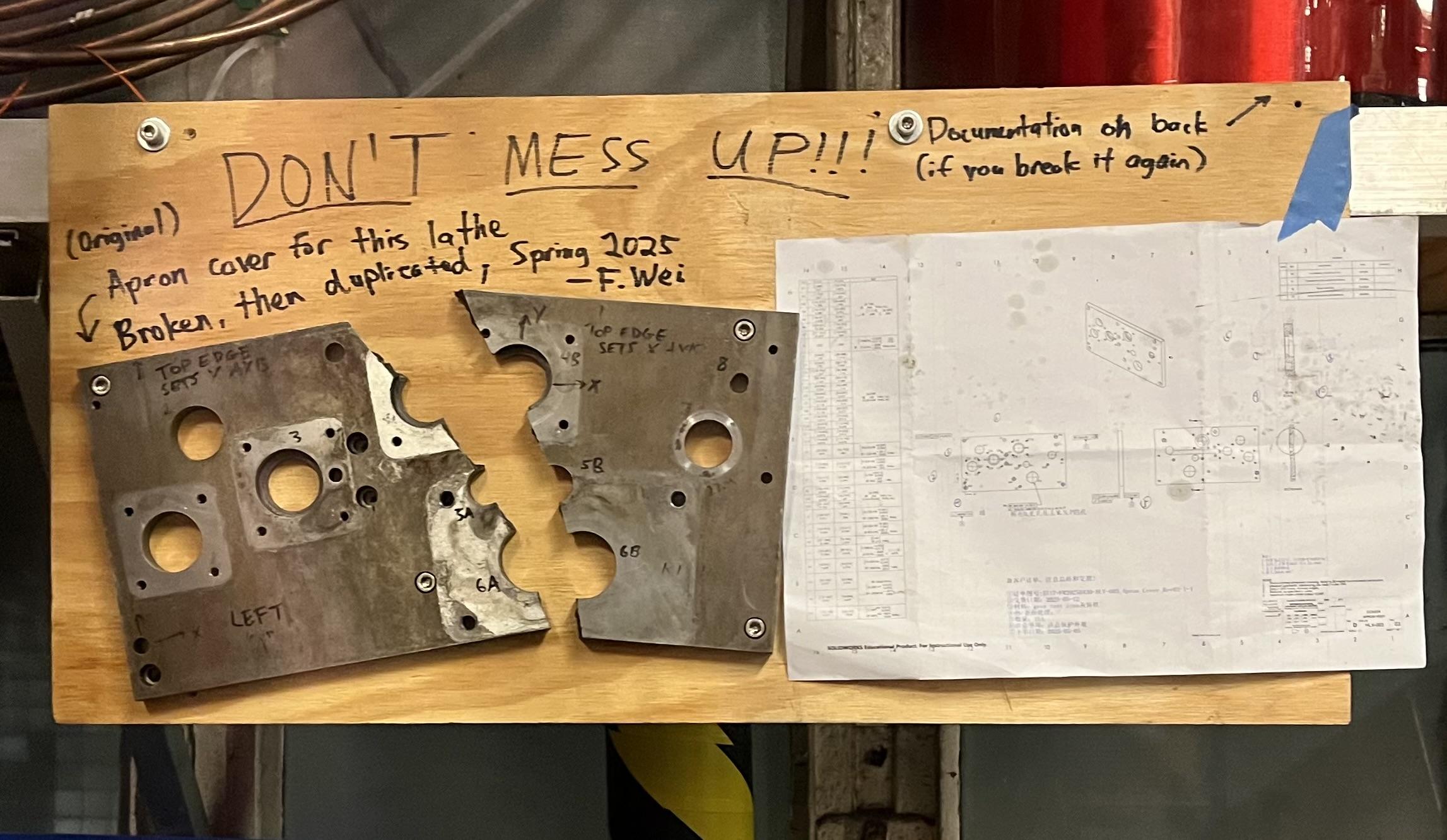
At this point, I evaluated the options for repairing my mistake. This model lathe hasn’t been manufactured for at least 65 years (the HLV was replaced by the HLV-H around 1960), but I figured it was worth asking Hardinge if they had replacements or drawings… no dice. I then asked an independent Hardinge repair specialist, who could only suggest we “upgrade to an HLV-H.” So that was a dead end, too. Casting repair techniques were also an option, but I decided it would be better to reverse engineer and duplicate the plate instead. Inspecting the cracked halves gave me hope, because at least geometrically, the part was fairly uncomplicated—it was just a ½” thick cast iron plate with several bores for supporting parts of the apron gear train. In fact, the only non-circular feature was a single milled slot which housed the sliding interlock bar.
By looking at the plate and piecing together information from the manuals and machinist forums, I was able to build a good mental model of how the apron functions, which was critical to understanding how to reverse engineer it. I reconstructed the following gear diagram that shows the gear arrangement in the apron, labeled with tooth counts and spacings:
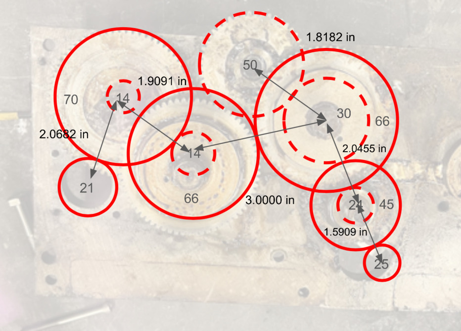
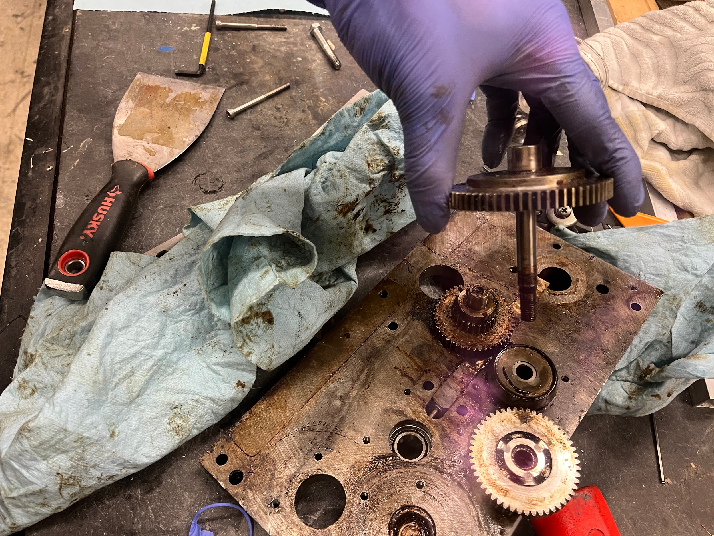
The function of the apron is to convert two inputs—rotation of the longitudinal handwheel gear (“21”, lower left in the image); and the power feed gear (“25”, lower right)—into two outputs: the rotation of the longitudinal pinion (“14”), which protrudes out the back of the apron to mesh with the rack; and the cross feed drive gear (“50”, upper center), which rotates the cross feed lead screw. The longitudinal handwheel is always meshed with the pinion gear, but the power feed can be clutched in and out using two friction clutches (the two gears labeled “66”), which are operated by the clutch levers on the front of the apron.
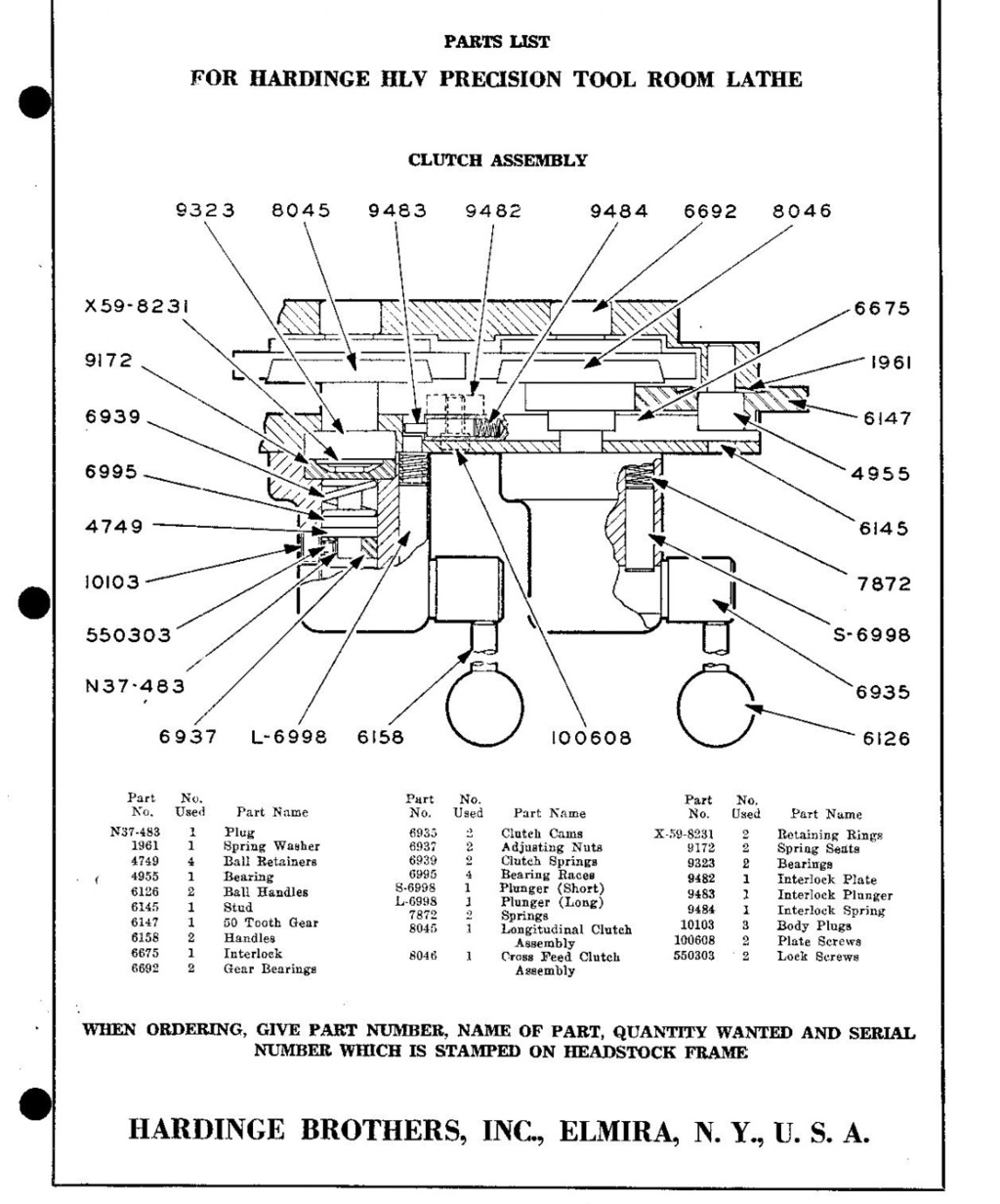
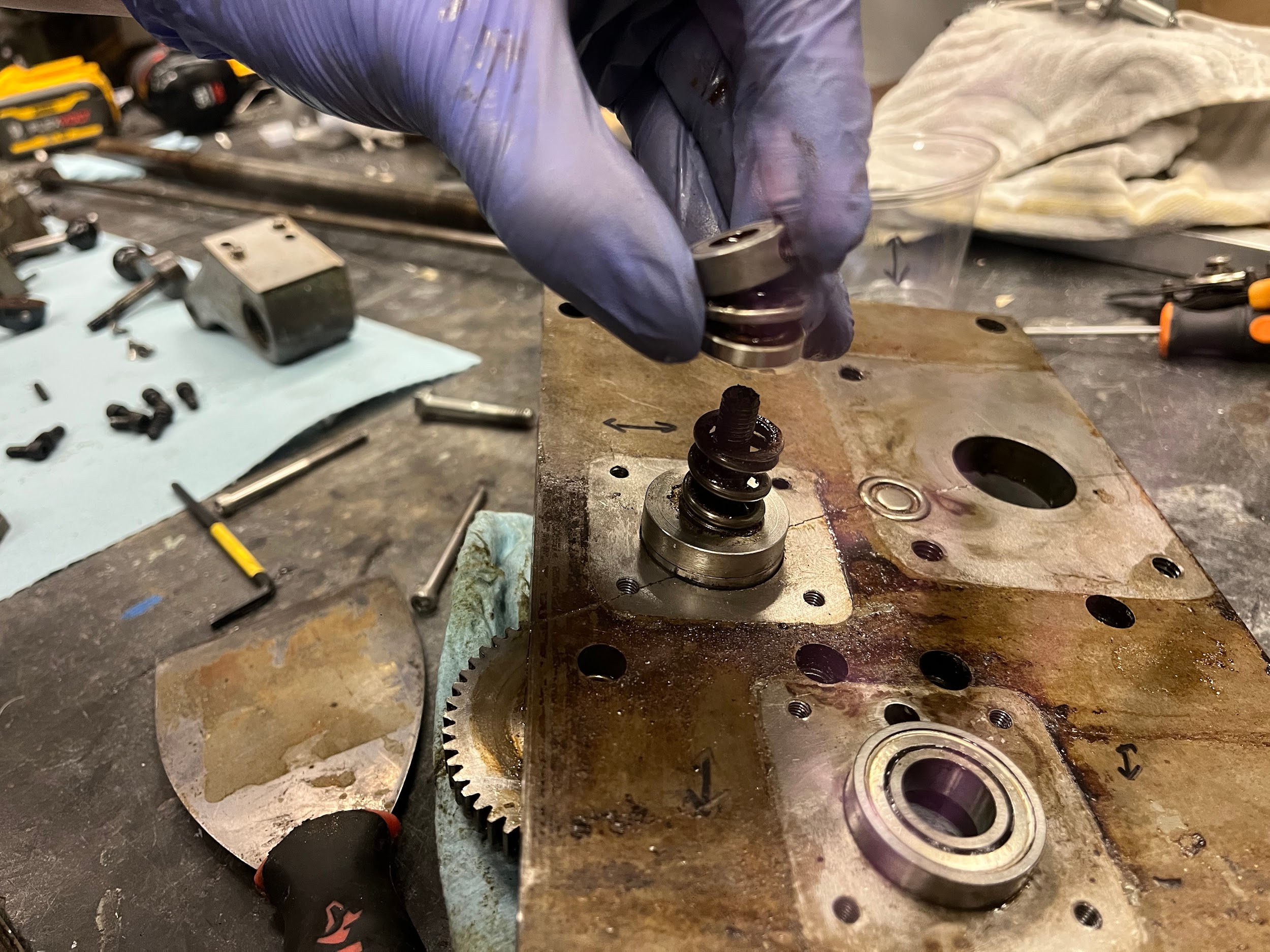
It took me quite a while to understand how these clutches function, which I’ll do my best to explain here to save anyone else the trouble. The clutch lever (p/n “6158” above) on the outside of the apron actuates a cam (6935) inside of the housing. The cam surface recedes further away from the apron face when the clutch lever is raised to engage the feed, and is driven closer when the lever is lowered to disengage. The total travel distance is quite small - less than 0.1”. The motion of the cam surface away from the apron face allows the clutch spring (6939) to extend, which applies a pulling force to a threaded stud which extends through the whole clutch pack to the large 66-tooth gear in the rear. This gear has a conical mating surface with the next gear forward, so when the two gears are compressed (via extension of the spring), they become coupled through friction. Disengaging the clutch does the opposite, compressing the spring and separating the clutch surfaces. There are also two thrust bearings (4749) in the assembly and a lockable adjusting nut (6937) on the stud that controls the spring compression, as well as miscellaneous spacers.
I found this whole mechanism to be quite ingenious, but also quite fussy—adjusting the clutch tension requires a convoluted process of peering into a service hole, using the power feed motor to rotate the gear train to expose the locking screw on the adjusting nut, and then using a 3/32” hex key to hold the nut in place, thus adjusting the spring tension while the feed motor rotates the shaft on which the nut is threaded. Quite intricate indeed—and I found that if this mechanism was misadjusted by even half a turn, the clutch would be permanently either disengaged or engaged. Not ideal.
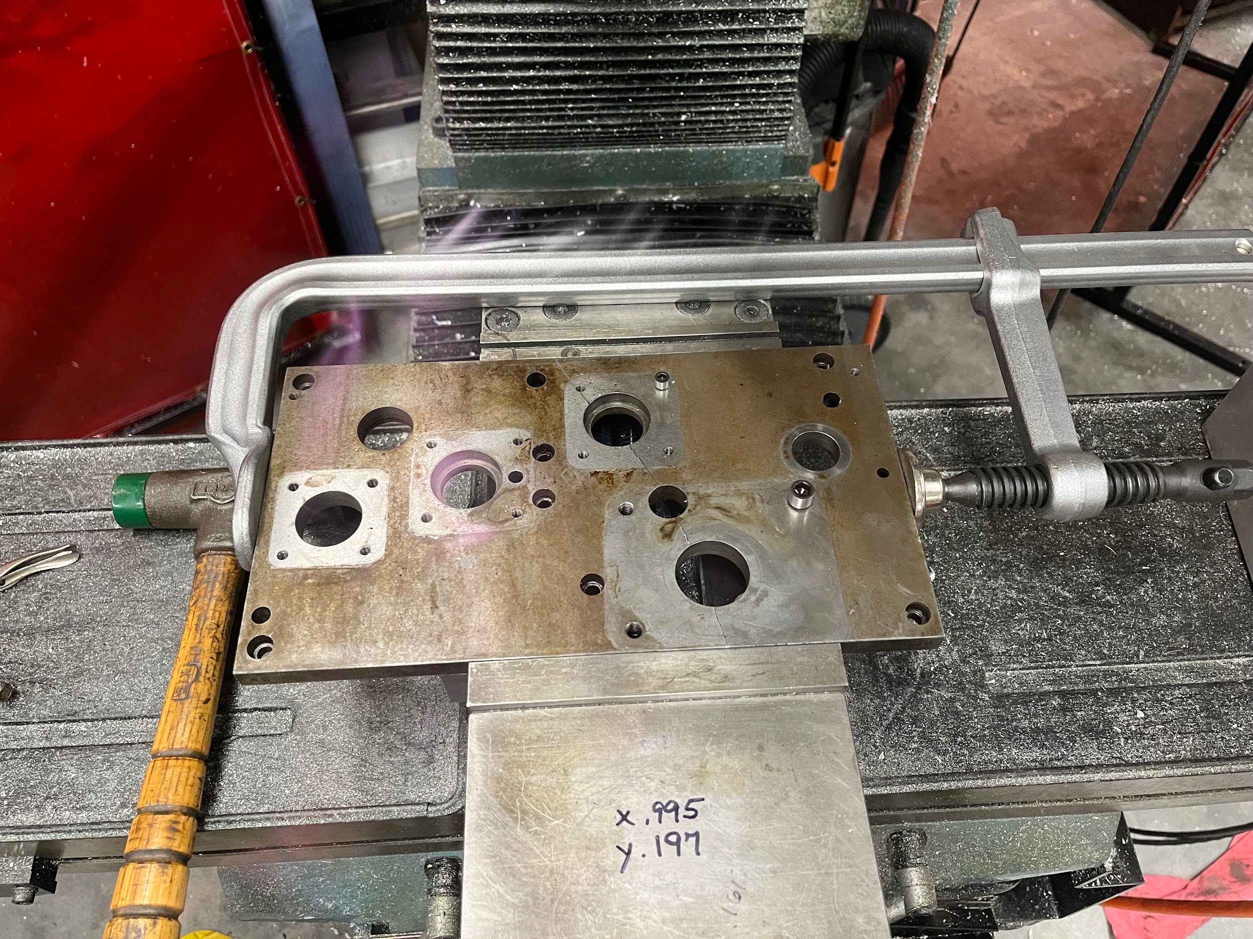
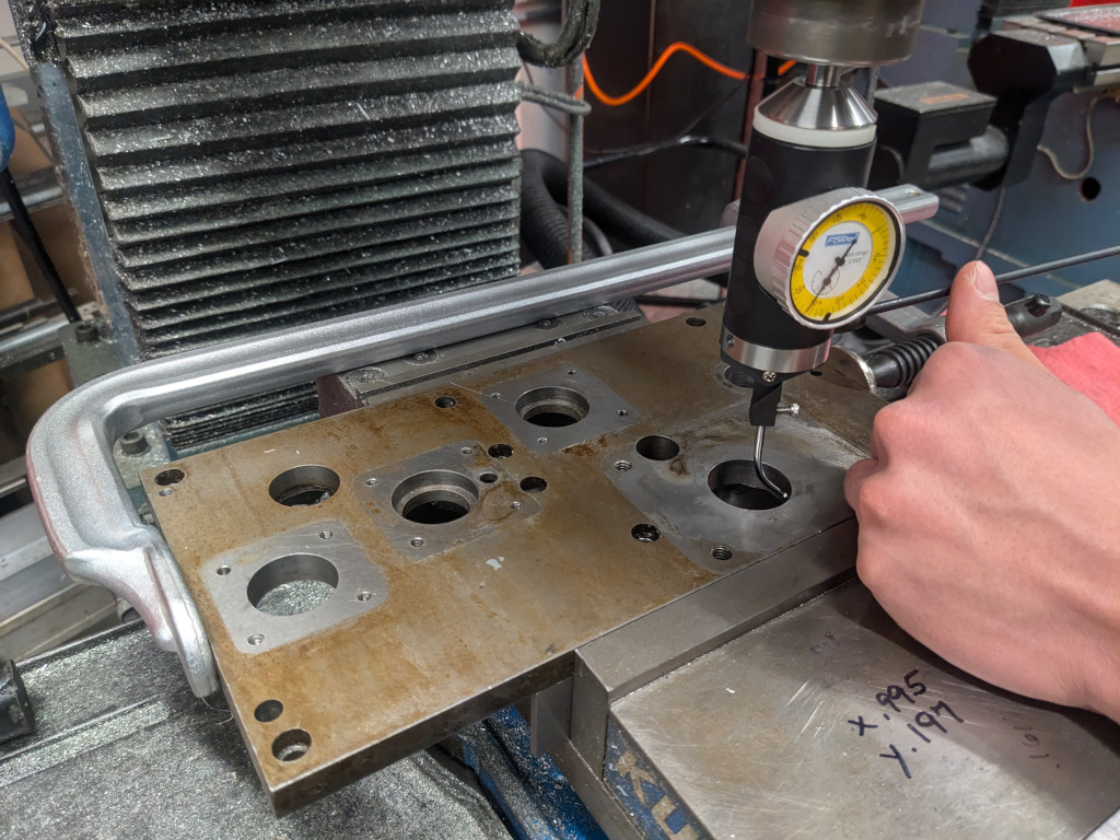
Anyway, armed with this understanding, I set about duplicating the plate. I first took careful hand measurements of the features of size. Besides the usual clearance and threaded holes, there were 4 bearing fits and several more close sliding fits for positioning the handwheel and power feed motor pinions, but overall this part was straightforward. The crux of the problem, however, was accurately measuring the hole positions for bearings that supported gears. These had to be quite accurate, as any misalignment could accelerate gear wear, or worse, cause the mechanism to bind entirely.
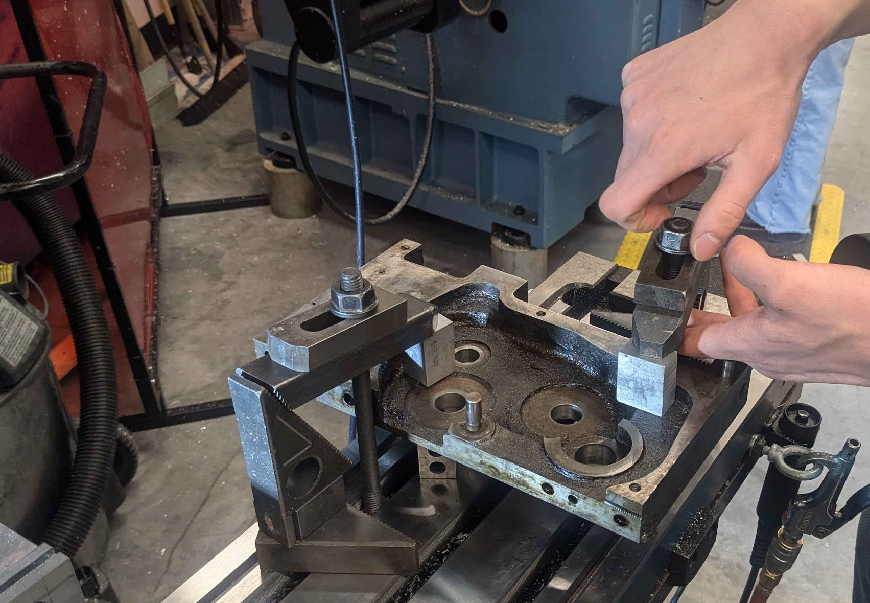
To measure these hole positions, I visited Mark Belanger’s 6C shop with Oliver Trevor, and first used a concentric dial indicator on a milling machine to locate each hole while the two broken halves were clamped together. As the crack extended through several of these bearing holes, we had to probe the left and right halves separately—sweeping the indicator through only half its arc—and then stitch the resulting data together.
Next, I probed the main apron casting. This was straightforward but nerve-wracking—as damaging it would render the entire lathe useless!
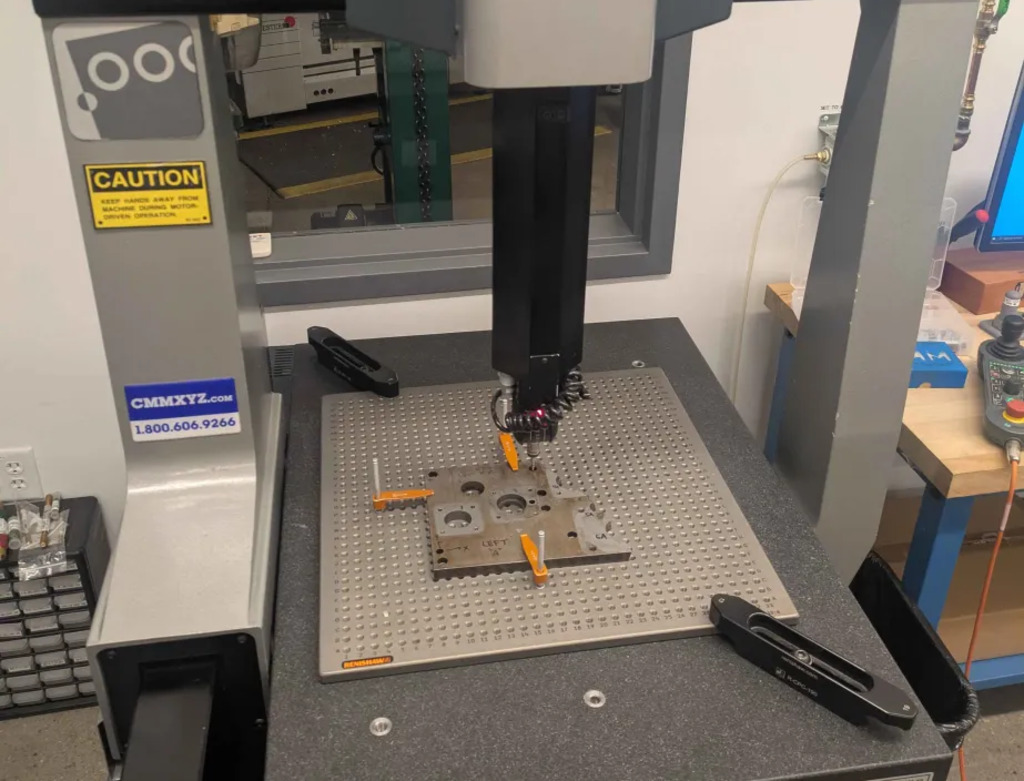
Finally, as a sanity check, I asked a friend to probe the three parts (two halves and main casting) on a coordinate measuring machine. (Thanks, Jonhenry!)
This gave me enough data to confidently reconstruct the hole positions to within a few thousandths—good enough for this application. As a cross check, it was suggested that I compare the gear-to-gear distances to the nominal values, as determined from the tooth counts and diametrical pitches of the meshing gears, and I found them to be in close agreement.
I drew up a Solidworks model of the plate, and as a final sanity check against the real part (and due to my lack of a dimensionally repeatable paper printer), I resorted to the below pictured method of precision inspection:
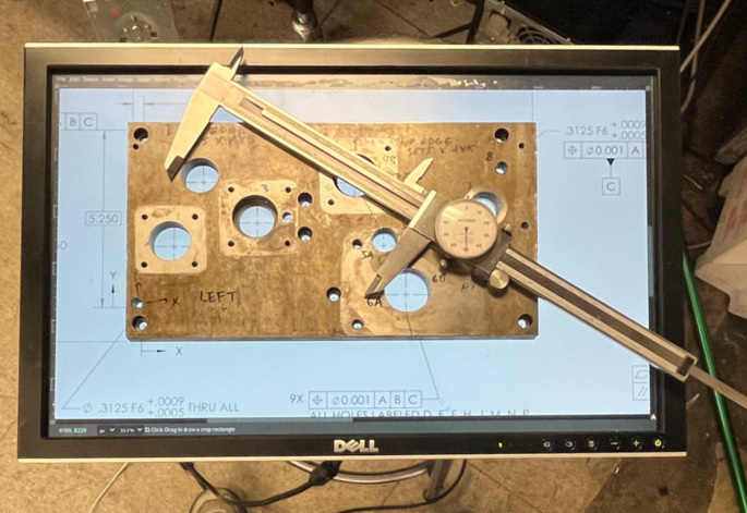
Yep, I used an old computer monitor to display the 2D drawing of the part, calibrated the image scale with calipers, and placed the real part on top. And it worked! I spotted a misplaced clearance hole with this method, but everything else was good to go!
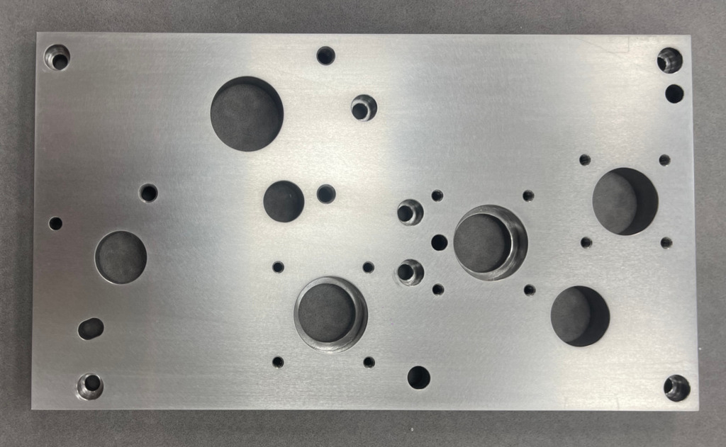
I made a toleranced drawing, and sent it off to my favorite contract machine shop to be machined in cast iron. Two weeks and an overseas wire transfer later, it arrived:
I then started reassembling the apron. I first took advantage of it being open to replace all the original bearings with modern equivalents (identified with the help of David’s blog—thanks!), and then reinstalled and lubricated all the gears with gear oil and the clutch surfaces with ATF.
To my surprise, nearly everything fit on the first try! There were some dowel holes which I needed to enlarge and a bearing that sat too deep, but a quick touch-up on the mill and a shim solved these problems.
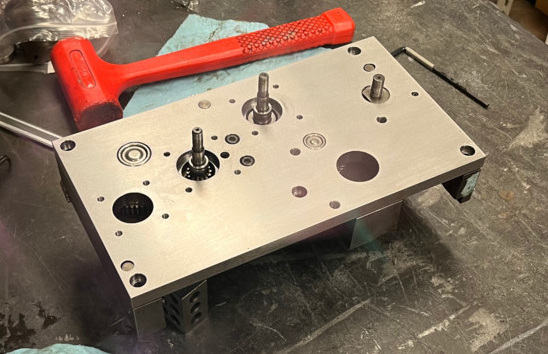
The clutches proved finicky as usual (I would advise roughly adjusting them before installing the apron on the lathe), and I had some issues with the gear train binding due to misalignment, but after some percussive persuasion with a mallet, everything ran smoothly. I then installed it on the lathe:
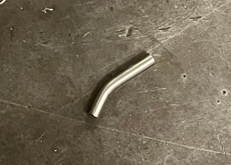
At this point, it felt like the finish line was in sight, but there were two last hurdles to clear—both to do with taper pins. (I now know they are essentially single use, but I tried to reuse them anyway…) First, I managed to bend the lead screw taper pin by turning the chuck with the pin half installed and the threading gearbox engaged. Oops. I ordered a new pin and that was quickly fixed.
Finally, I found that fully installing the half nut lever’s taper pin would cause the lever to become extremely tight. By this point, I was ready to call things done, so I just cut the pin shorter with an angle grinder such that it didn’t protrude, even when half seated. Problem solved.
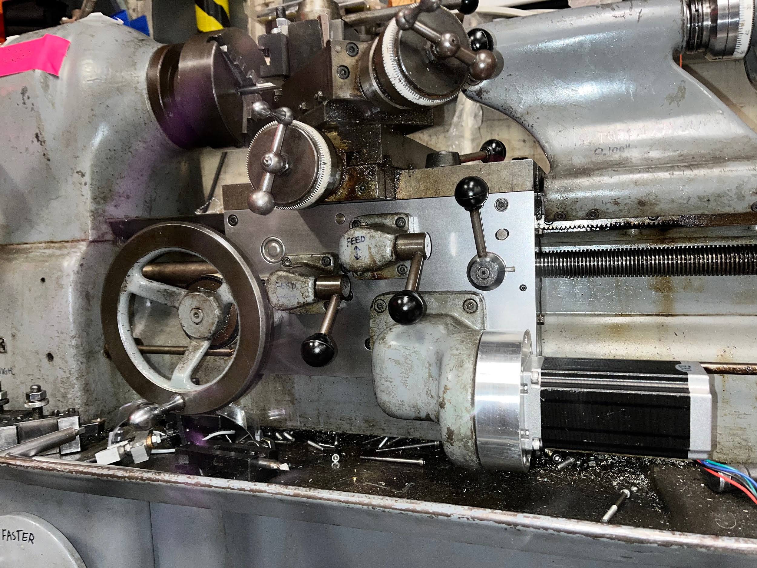
After this circuitous journey, I had finally arrived at my original objective: a fully functioning lathe—with both power feeds working once again. It felt good to clean up the mess that had accumulated around the lathe, oil it back up, and to place it back in service in MITERS… and hopefully it stays that way!
I’m still not sure exactly why this is the case—online forums claim it’s because a gear is in the way, but I don’t think this is true. While there is a gear that protrudes upward from the apron, it is not axially constrained by the apron cover. My current theory is that some solidified gunk under the cross slide was interfering with the top of the apron cover, but I’m not fully confident in this.↩︎